NEW! The Gist (APR-24) | E-BOOKS |
(Download) UPSC IES Exam Paper - 2018 "Electrical Engineering Paper - 2"
![]()
(Download) UPSC IES Exam Paper - 2018 "Electrical Engineering Paper - II"
Exam Name: Engineering Services Exam (IES)
Paper : ELECTRICAL ENGINEERING Paper - II
Year: 2018
File Type: PDF
ELECTRICAL ENGINEERING
Paper - II
Time Allowed : Three Hours
Maximum Marks : 300
QUESTION PAPER SPECIFIC INSTRUCTIONS
Please read each of the following instructions carefully before attempting questions.
There are EIGHT questions divided in TWO Sections.
Candidate has to attempt FIVE questions in all.
Question Nos. 1 and 5 are compulsory and out of the remaining, THREE are to be attempted choosing at least ONE question from each Section.
The number of marks carried by a question / part is indicated against it.
Assume suitable data, if considered necessary and indicate the same clearly.
Unless otherwise mentioned, symbols and notations carry their usual standard meanings.
Attempts of questions shall be counted in sequential order. Unless struck off, attempt of a question shall be counted even if attempted partly.
Any page or portion of the page left blank in the Question-cum-Answer Booklet must be clearly struck off.
Answers must be written in ENGLISH ONLY.
SECTION ‘A’
1. (a) A single-phase AC voltage controller is feeding a resistive load of 26.45 2 from an AC source of 230 V, 50 Hz. Compute the firing angle to deliver 1000 W to the load. Also compute the p.f. at which this power is delivered. Draw a neat circuit diagram and waveforms of voltage at load terminals with current flowing in the load.
(b) An open-loop system G(s)=1/s2 (ts+1) , is placed in cascade with a proportional and derivative controller K(s) = (1 +Tds). If their unity feedback closed-loop system oscillates at a frequency of Ö2 rad/second, find the ranges/ values of the system and controller parameters, i.e., ranges/values of K, Td and t.
(c) Determine the mechanical time constant of rotor of an electrical machine in terms of its moment of inertia J kg-m2 and windage cum friction coefficient fN-m/rad/s. Also explain the method to determine mechanical time constant experimentally in laboratory.
(d) An electric train running between two stations A and B, 10 km apart and maintained at voltages 550 V and 500 V respectively, draws a constant current of 600 A. The resistance for both go and return conductors is 0.04W/km. Find the point of minimum potential between the stations, the voltage at that point and currents drawn from both the stations at that point.
(e)
2. (a) A single-phase full bridge inverter is used to produce a 50 Hz voltage across a series R-L load (R = 10 W and L = 20 mH) using bipolar PWM. The DC input to the bridge is 380 V, the amplitude modulation ratio ma = 0.8 and frequency modulation ratio mf = 21. Consider dominant harmonics to be frequency dominant and its nearby side frequencies (both sides). Assume normalized Fourier coefficient for ma = 0.8 to be 82% for dominant harmonic frequency and 22% for the nearby side frequencies.
Determine
(i) amplitude of 50 Hz component of output voltage and
current;
(ii) power absorbed by the load resistor;
(iii) THD of the load current.
Also compare the amplitude of 50 Hz component of output voltage with square wave and quasi-square wave output.
(b) A 3-phase, 6-pole, 460 V, 50 Hz induction generator operates at 480 V. The generator has its rated output power of 20 kW. It is driven by a turbine at a speed of 1015 r.p.m. The generator has the following electrical parameters :
R1 = 0.2W R2 =
0.15W Rsh = 320W
X1 =1.2W X2 = 1.29W
XM = 42W
Find the active power delivered by the generator and reactive power it requires from the system to operate.
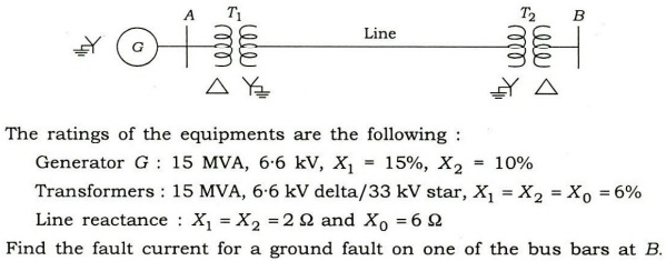
(c) (i) Under what condition a single line-to-ground fault at the terminals of a generator can be more severe than a 3-phase symmetrical fault at the same location?
(ii) A 3-phase power system is represented by one-line diagram as shown in the figure below :
3.(a)

4. (a) (i) What do you mean by grading of cables? What are the methods of grading?
(ii) Derive the condition for minimum value of gradient at the surface of the conductor.
(iii) Determine the economic overall diameter of a single-core cable metal sheathed for a working voltage of 75 kV, if the dielectric strength of the insulating material is 60 kV/cm.
(b) A 400 V, 50 Hz, 6-pole, 960 r.p.m., Y-connected induction motor has the following parameters per phase referred to stator :
r1 = 0.4W; = r2 =0.2W; x1 = x'2 = 1.5W; Xm = 30W
The motor is controlled by a variable frequency inverter at a constant flux of rated value for operation below synchronous speed, super-synchronous operation region flux is weakened by keeping voltage constant at rated value. Assume straight line for torque vs. slip characteristics for slip s < Sm (motor region) and s>sm (generator region). The connected load on the shaft is constant torque type.
Calculate the inverter frequency and current drawn by the stator when torque on the shaft is half-rated while motoring at 500 r.p.m.
(c) Why is the waveshape of magnetizing current of a transformer non-linear? Explain the phenomenon of in-rush magnetizing current and derive its expression in terms of a, the angle of the voltage sinusoid at t = 0 and or, the residual core flux at t = 0.
Use the graph sheet to show non-linearity of current from the assumed 0-i diagram of magnetic core of the transformer.
Study Material for IAS (UPSC) General Studies Pre. Cum Mains
SECTION-B
5. (a) A DC motor has an armature resistance of 0.5W and Ko of 3 Vs. The motor is driven by a single-phase thyristorized full converter. The input to the converter is an AC source of 230 V, 50 Hz. The motor is used as a prime mover of a forklift. In the upward direction, the mechanical load is 69 Nm and the triggering angle is a = 15°. In the downward direction, the load torque is 180 Nm. Calculate the triggering angle required to keep the downward speed equal in magnitude to upward speed. Assume continuous motor current for all operation. Also calculate the triggering angle to keep the motor at holding position while it was moving upward.
(b) The primary side of an ideal transformer (having 400 turns in primary winding and 720 turns in secondary winding) is excited by a 1000 V, 50 Hz AC source. The secondary of the transformer is connected to a resistive load of 80 kW. There is one tapping in secondary winding at 480 turns and this tapping is supplying a pure inductive load of 100 kVA. Determine the primary current and its power factor.
(e)
6. (a) A 20 kW, 500 V DC shunt motor (having 90% full-load efficiency) has 40% armature copper losses of its full-load losses. Calculate the resistance values of a 4-section starter suitable for limiting starting current between 120% to 200% of full-load current. Assume field resistance of 250W
(b) (i) Differentiate between characteristic impedance and surge impedance of a line. What do you mean by surge impedance loading (SIL) of a transmission line?
(ii) A three-phase, 50 Hz transmission line is 400 km long. The voltage at the sending end is 220 kV. The line parameters are r = 0.125 ohm/km, x = 0.4 ohm/km and y=2.8x10⁻⁶ mho/km. Find the sending-end current and receiving-end voltage when there is no load on the line. Make a comment on the value of receiving-end voltage.
(c) A boost converter is required to have an output voltage of 48 V and supply a load current of 5 A. The input varies from 12 V-24 V. A control circuit adjusts the duty ratio to keep the output voltage constant. Select the switching frequency to be 200 kHz. Determine a value of inductor such that the variation in inductor current is no more than 40% of average inductor current for all operation. Prescribe a suitable value of capacitor such that output ripple is no more than 2%.
(c) (i) In case of a circuit breaker, define the terms 'restriking voltage and RRRV', and express their maximum values in terms of system voltage.
(ii) Which circuit breaker is preferred for voltages 132 kV and above?
(iii) In a 132 kV system, the reactance per phase up to the location of circuit breaker is 5W and capacitance to earth is 0.03 uF. Calculate the maximum value of restriking voltage, the maximum value of RRRV and frequency of transient oscillation.
(c)

Study Material for IAS (UPSC) General Studies Pre. Cum Mains
Click Here to Download PDF
<< Go Back To Main Page

Whats Hot!
Downloads
- New! THE HINDU, YOJANA, PIB PDF
- New! UPSC PRELIM Papers 2004-2023
- IAS परीक्षा पेपर in Hindi 2004-2023
- UPSC Syllabus PDF Download
- New! IAS MAINS Papers 2010-2023
- PDF Study Notes for UPSC (Hot!)
- E-books PDF Download
- NCERT Books Download | NCERT Hindi PDF
- New! UPSC MAINS SOLVED PAPERS PDF
- OLD NCERT PDF
- UPSC 2024 Exam Calendar